This web page was produced as an assignment for an undergraduate course at Davidson College.
Review Paper 2
The authors of this study investigated the possibility of making more sophisticated genetically engineered logic switches that modulate RNA polymerase activity (and therefore gene expression). They created logic switches modeled after the Boolean logic gates found in microchips and used to filter search engine results. These are comprised of combinations of terminator sequences that block RNA polymerase progress along template DNA, as well as recombination sites within which the terminators are nested. These recombination sites facilitate gate activation by inverting or excising terminators, allowing or blocking further transcription. The molecules used for activating the logic gates are DNA integrases isolated from two bacteriophages: TP901-1 and Bxb1, which in those systems are used to insert viral DNA into the host genome during the lysogenic cycle. The gates can be reset by using recombination directionality factors (RDF’s), making them reversible. The various components of these three-terminal “transcriptors” are compatible with a wide variety of organisms, allowing modulation of transcription in each.
The gates and integrases were located on plasmids. The plasmids containing the integrases were activated by exogenous arabinose and anhydrotetracycline for the TP901-1 and Bxb1 integrases respectively. The plasmids containing the gates also featured a strong prokaryotic promoter upstream of the gate, and Green fluorescent protein (GFP) as a reporter downstream of the gate. GFP was a reporter for transcription, and the authors expected that greater fluorescence would result from gate-activated amplification. The authors were successful in predicting and modulating transcription levels given by the various logic gates that they designed (Fig 2), as well as demonstrating the digital (on/off) nature of gated transcription in most of the gates (Fig 3). The authors highlight decoupling the activation of gates from the input or output (transcription) as one of the greatest of achievements of this study.
My Reaction
Overall I am very impressed with the experimental design of this investigation as well as the results. The architecture of the gates is ingenious (Fig 1), the correlation between predicted amplification and observed amplification impressive (Fig 2), and the amplifying effect of the gated activation undeniable (Fig 3). Following Figures 2 and 4, the increase in expression for an activated gate seems reliable enough to incorporate each as gates of equal output for varying input in a biological circuit. The data in Figure 3 are the source of my skepticism. While the data highlighting the digital nature of the XOR gate show a very clean, abrupt switch to an activated state and higher transcription, the data for the other gates are not nearly as smooth given the same control signal concentration change.
Varying “digitization error rates” suggest that not only are some logic gates more dependable than others, but that not every gate can be expected to perform reliably 100% of the time. Depending on the intended application of a biological computer, these error rates might make such a computer unreliable. I wonder what the error rates are for gates in typical silicon computer chips. On the other hand, it seems likely that an average taken from a large enough population of cells featuring the same gate would yield reliable responses. What implications would the need for such robust averages be for the computing speed of a biological computer? Could the merits of its capacity outweigh that of speed?
Will each circuit in a biological computer require that new thresholds for on/off be established due the varying conditions? That is, how difficult will it be to optimize each new gate and control signals, as the authors did in Figure 3 C-D? The difference in the response to the two different control signals also introduces variability that may be difficult to standardize across several different integrated circuits. Above all, there may be a certain degree of error that is unavoidable due to the stochastic nature of cellular environments and gene expression. The authors acknowledge these concerns in their concluding statements.
Figure it out! Figure Summaries
Genomics Page
Biology Home Page
___________________________________________________________________________________________________________
Figure 1: General architecture of 3-terminal gates
RNA polymerase encounters a gate, which is a sequence of DNA containing one or more terminators nested within one or more layers of recombination sites. An upright terminator blocks further transcription by RNA polymerase. Terminators can be inverted, allowing RNA polymerase to continue unhindered, and can also begin inverted. Different integrases causes flipping at different recombination sites (colored triangles), allowing for the construction of three-terminal gates: 1st terminal: RNA polymerase, 2nd terminal: integrase 1, 3rd terminal: integrase 2. From these building blocks the Boolean logic can be replicated. Panel E shows a complete XOR gate.
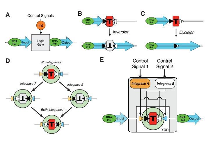
Figure 2: Will the architecture of each Boolean gate predict the GFP expression?
Six Boolean gates were constructed using the building blocks described in figure 1. (“Gate”). The architecture of each using those building blocks is shown (“Architecture”). Of note is the permanent constitutive promoter featured in the NAND architecture, which is required to achieve amplified output when only the integrases for the terminator inversion are present. “Predicted” shows predicted GFP expression among populations of cells exposed to varying concentrations of each integrase (via controllers: arabinose and anhydrotetracycline) simultaneously. “Population Measurements” shows very clear similarity between the predicted and observed GFP expression. Single cells show similar clarity. Very noteworthy is the red line indicating a common threshold for distinguishing low GFP expression and high GFP expression. Overall the gate design is predictive of gene expression.
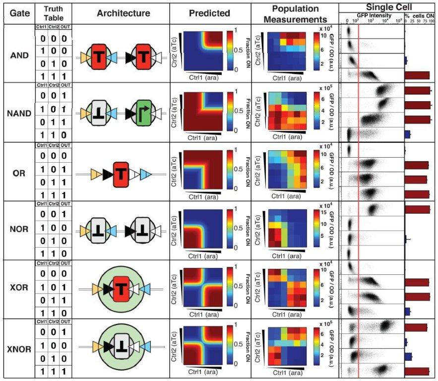
Figure 3: Is gate activation digital (on/off) or gradual?
This figure reports the degree to which each unique gate architecture will switch abruptly to an activated state given a change in control signal concentration (proportional to integrase concentration) as compared with control plasmids. While 0.2 to 2ng/mL anhydrotetracycline and 1E-4 to 0.5E-2 arabinose were sufficient changes to result in digital responses for the XOR gate (A-B), the same changes yielded mixed results in the other gates (C-D). The error reporting within and above the frames of C-D help to quantify the degree to which each switch is digital under the given conditions. The authors decide that AND, OR, XOR, and XNOR are digital with respect to anhydrotetracycline, and AND, OR, NOR, XOR, an XNOR with respect to arabinose. The gates are variably digital, casting some doubt upon their proposed performance in biological computers.
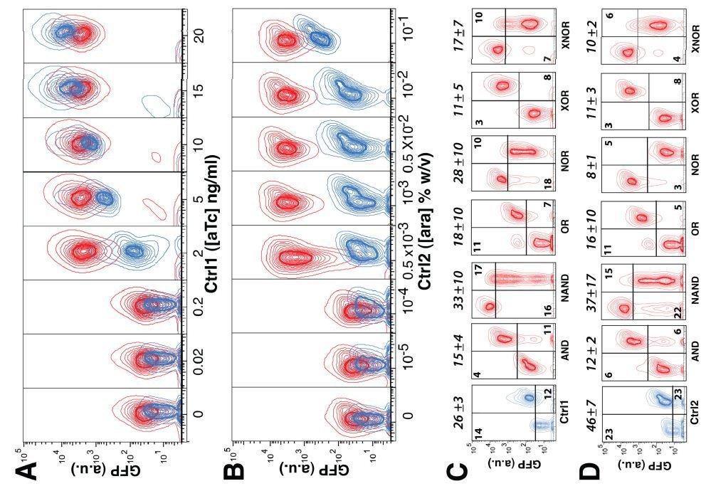
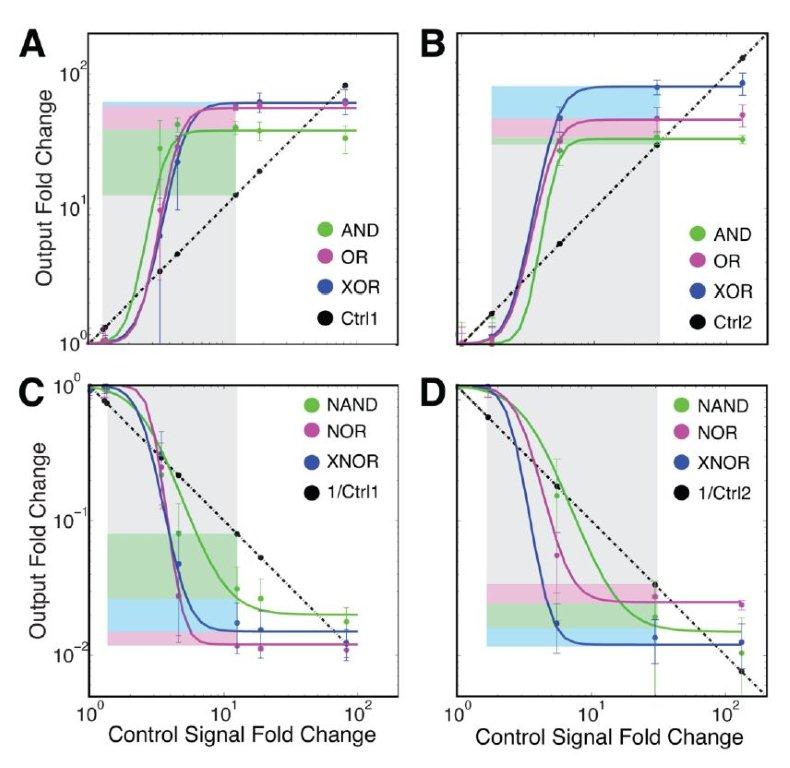
Figure 4: Do the gates abruptly amplify GFP expression as compared to the control?
These plots depict the increase in GFP expression that results from exposing each of the gate architectures in question and the control to increasing concentrations of the control signals. In A and B, the plasmids are responding to activation by each individual control signal. In B and C, the amplifier gates are inverted, resulting in reduction of GFP expression. Both the amplification and reduction show abrupt increases and decreases for each of the gates displayed, further supporting the digital nature of their activation. The color-coded boxes seek to distinguish the degree of amplification and reduction between each gate architecture, but the overlapping error bars in most cases render those distinctions unreliable. That each of the gates displayed in this plot achieves a significant amplification over the control is support for their viability within a bioengineered circuit.
Genomics Page
Biology Home Page
© Copyright 2013 Department of Biology, Davidson College, Davidson, NC 28035